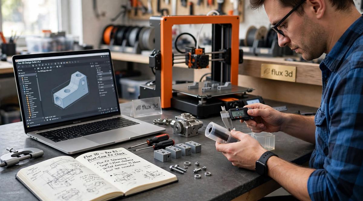
A printed shaft will not reliably fit a hole just because both have the same diameter in CAD. Matching nominal dimensions leave no designed clearance, and printing can change the size, shape and surface of both features. A joint that starts easily may also bind halfway through its engagement length.
The practical way to manage 3D printing tolerances and clearances is to test the uncertain interface before printing the complete assembly. Make small, representative samples, measure both mating features, check their movement and revise one variable at a time. These samples are often called test coupons.
This workflow helps identify a suitable fit for a particular geometry and production setup. It does not produce a universal clearance value for every printer or material.
Tolerance and clearance: what is the difference?
Dimensional tolerance is the permitted variation in a dimension. A shaft specified as 10.00 mm ±0.05 mm may measure from 9.95 mm to 10.05 mm and still meet that dimensional requirement. Specifying this tolerance does not establish that a printing process can consistently achieve it.
Clearance is the space between mating features. For ideal concentric cylinders:
- Diametral clearance = hole diameter − shaft diameter.
- Radial clearance = diametral clearance ÷ 2.
A 10.20 mm hole around a 10.00 mm shaft therefore has 0.20 mm diametral clearance and, when centred, a 0.10 mm radial gap. Always state whether a clearance is across the diameter or per side.
Check the worst-case dimensions
Suppose a drawing specifies a 10.20 mm ±0.05 mm hole and a 10.00 mm ±0.05 mm shaft. The minimum diametral clearance is:
Smallest permitted hole − largest permitted shaft = 10.15 − 10.05 = 0.10 mm
For a guaranteed clearance fit based on these size limits, the smallest permitted hole must exceed the largest permitted shaft. However, actual movement also depends on form, alignment, surface condition and engagement length.
These numbers explain the geometry; they are not recommended printing allowances. Appropriate values depend on the process, material, geometry, orientation and intended function.
Define what a successful fit must do
Before changing dimensions, write down the required behaviour. “Fits correctly” is too vague to guide a revision.
- Movement: Must the shaft rotate, slide, remain fixed or be removed occasionally?
- Assembly: Should insertion require only light hand pressure, or is a controlled assembly force acceptable?
- Engagement: How far must the shaft enter, and must it reach a shoulder or stop?
- Play: How much movement is acceptable at the working end?
- Use conditions: Will load, repeated movement or operating temperature affect the joint?
- Finishing: Must it work without dimensional finishing, or is drilling, reaming or sanding allowed?
For example, a prototype requirement might be: “The shaft must enter the full 20 mm engagement length by hand, rotate without sticking and show no unacceptable movement at the attached lever.” The engagement length is specific to this example, not a general design rule.
If play or insertion force matters to performance, define a measurable limit and a repeatable way to check it. A subjective hand check can screen candidates, but it may not be sufficient for final acceptance.
Print critical interfaces before complete assemblies
A test coupon isolates the feature you are uncertain about. For a shaft-and-hole joint, this could be a short section of the housing containing the bore, plus the mating shaft or the actual purchased pin.
Keep the coupon small, but preserve the details that influence fit:
- Local wall thickness and nearby ribs, bosses or openings.
- Full engagement length where practical.
- Entry chamfers, shoulders and end stops.
- Intended print orientation and relevant support-contact surfaces.
- Material, print profile and finishing route.
A thin plate with a hole may not represent a long bore in a thick housing. Similarly, a short pin may pass through an opening even though a longer shaft binds because of taper, distortion or misalignment.
If the shaft is a purchased metal component, test with that component rather than a printed substitute. If both parts will be printed, include both in the test plan.
Build labelled hole-and-shaft test coupons
Start with a small set of dimensional variants around a plausible starting point agreed with your print provider or based on previous work with the same setup. Avoid changing the hole and shaft dimensions simultaneously during the first comparison.
- Fix one mating feature. Keep the shaft design unchanged while varying the hole diameter, for example.
- Create several candidates. Use distinct dimensions that allow you to compare tighter and looser fits.
- Label every coupon. Use IDs such as H01, H02 and H03, positioned away from contact surfaces.
- Save the CAD revision. Link each ID to its nominal dimensions and exported print file.
- Print under representative conditions. Keep material, profile, orientation and finishing consistent across the comparison.
The following table is an invented worksheet example, not measured test evidence or a recommended clearance series. It shows how nominal dimensions, measured dimensions and functional observations should be recorded separately.
| Coupon | CAD hole diameter | Measured hole diameter | Measured shaft diameter | Calculated diametral clearance | Example fit observation |
|---|---|---|---|---|---|
| H01 | 10.10 mm | 10.04 mm | 10.02 mm | 0.02 mm | Starts, then binds before full insertion |
| H02 | 10.20 mm | 10.14 mm | 10.02 mm | 0.12 mm | Reaches full depth and rotates by hand |
| H03 | 10.30 mm | 10.24 mm | 10.02 mm | 0.22 mm | Moves freely, but play exceeds the intended limit |
These simplified readings do not capture the entire shape of either feature. H01 could bind despite a positive measured clearance because a local restriction, rough surface or alignment error was not captured by the measurement. H02 is a candidate for repeat testing, not an automatically approved design.
Keep orientation and finishing representative
Print orientation and dimensional accuracy must be considered together. Rotating a part changes how its features are formed and can change support placement and surface condition. Orientation, surrounding wall thickness and nearby geometry can also affect hole formation.
Do not validate an upright bore and then assume the same result for a horizontally printed production part. If you change orientation, treat that as a new test condition. Likewise, do not transfer numerical guidance from one printing process directly to another.
Test parts in their intended finished condition. For resin parts, follow the specified washing, drying and post-curing procedure, then allow them to cool before measurement and fit testing. Keep these steps consistent across candidates.
If sanding, drilling or reaming is planned, document the operation and evaluate the finished interface. If it was not planned, record any adjustment separately. A hand-sanded success is not evidence that the unadjusted part met the requirement.
Measure dimensions and check functional fit
Measurement helps explain the result; assembly testing checks whether the interface works. Use both.
Measure both mating features
- Clean the measuring faces and check caliper zero.
- Align the jaws correctly and apply light, consistent pressure.
- Repeat readings rather than relying on one measurement.
- Measure the shaft at several positions along its engagement length and in different directions.
- Check the hole at accessible depths and directions; record where access prevents inspection.
Small holes require particular care because caliper internal-jaw geometry and alignment can introduce error. Where the required distinction is too small for a reliable caliper check, use a suitable bore-measuring method or gauge. Do not assume a displayed decimal place represents equivalent measurement accuracy.
Check the full movement
Insert the shaft without forcing it and note where resistance begins. Check full insertion depth, rotation or sliding as required, removal and unwanted play. Use a consistent test method across candidates.
Binding only near the entrance may suggest an entry defect. Binding deeper inside may suggest taper, distortion, roughness or misalignment. These observations guide inspection; they do not establish the cause by themselves.
Track revisions and change one variable at a time
Use a simple worksheet so that the successful fit can be reproduced. This is a practical record, not a formal inspection standard.
- Design revision and coupon ID.
- Nominal hole and shaft dimensions.
- Measured dimensions, measurement locations and tools.
- Printer, material and print-profile identifier.
- Orientation and relevant support details.
- Cleaning, curing and dimensional finishing.
- Fit result, observed failure and next planned change.
Change one variable between comparisons whenever possible. If you enlarge the hole, rotate the part and sand the shaft in the same revision, you cannot tell which change solved the problem.
Repeat the selected candidate in another print run before committing to the complete assembly. One successful pair demonstrates that pair, not consistent production capability. If printed parts must be interchangeable, cross-check multiple holes and shafts rather than testing only matched pairs.
Confirm the result in the complete assembly
Coupon success is a reason to proceed to full-assembly testing, not final proof of fit. Larger parts introduce factors that an isolated sample may not capture: overall distortion, multiple locating features, accumulated dimensional variation and restricted assembly access.
Print the complete assembly using the intended setup. Check assembly sequence, fastener access, alignment, full travel and movement under representative use conditions. Include the actual mating hardware where possible.
If the complete assembly fails, record how its behaviour differs from the coupon. The next useful test may need to include two aligned bores, a mounting face or a larger housing section rather than another isolated hole.
Frequently asked questions
How much clearance should I leave between 3D printed parts?
There is no universal value. Start with guidance specific to the process and material, then test labelled variants that preserve the intended geometry, orientation and finishing. Select against a defined functional requirement.
Is clearance measured per side or across the diameter?
Either convention may be used, so state it explicitly. For ideal concentric cylinders, diametral clearance is the hole diameter minus the shaft diameter. The radial gap is half that value.
Should I measure resin parts before or after curing?
For final fit evaluation, measure after the required washing, drying and post-curing steps, once the parts have cooled. Earlier measurements can help investigate changes but do not replace finished-part inspection.
If you need a custom part or prototype, share your mating geometry, required movement and planned finishing with Flux3D so the first print can target the interface that matters.
Flux3D Team
Build it with Flux3D
Need a custom part or prototype?
Flux3D can help turn your design into a practical 3D-printed part.
Get an instant quote